
This is going to be a lengthy post, one I’ve been wanting to do for a while, since there is not much information out there on this type of setup.
First off, let me explain the title real quick. “Juniper SSG Double Dual Homed VPN” means that we have 2 sites, e.g. branch and a main office and that both sites have two different internet connections for failover. We want to create a VPN between these 2 sites. It will look like this:
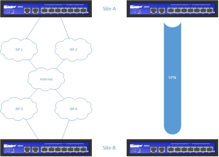
Juniper SSG firewall devices could be a perfect fit for a branch connecting to a main facility/datacenter. They have a bunch of features and are as stable as a rock. In this post, I’m going to lay out the setup and configuration to create a double dual homed VPN setup. We will be using a vrouter (vrf) per ISP, OSPF going over the VPN tunnels for the routing failover and normal VPN functionality.
This is the information we’ll be using:
Site-A
– ISP 1: SSG IP 1.1.1.2 on ethernet0/0 and gateway IP: 1.1.1.1
– ISP 2: SSG IP 1.1.2.2 on ethernet0/1 and gateway IP: 1.1.2.1
Local subnets
– 10.1.1.1/24 on ethernet0/2 (primarily outbound via ISP1)
– 10.1.2.1/24 on ethetnet0/3 (primarily outbound via ISP2)Site-B
– ISP 1: SSG IP 2.2.1.2 on ethernet0/0 and gateway IP: 2.2.1.1
– ISP 2: SSG IP 2.2.2.2 on ethernet0/1 and gateway IP: 2.2.2.1
Local subnets:
– 10.2.1.1/24 on ethernet0/2 (primarily outbound via ISP1)
– 10.2.2.1/24 on ethetnet0/3 (primarily outbound via ISP2)
We will start by configuring the WAN interfaces and putting them into their vrouters and allowing a failover between the 2 ISPs:
Site-A
set vrouter name “ISP1-vr”
set vrouter name “ISP2-vr”set vrouter “ISP1-vr”
set route 0.0.0.0/0 interface ethernet0/0 gateway 1.1.1.1
set route 0.0.0.0/0 vrouter “ISP2-vr” preference 200 metric 200
set route 10.1.2.0/24 vrouter “ISP2-vr” preference 1
exit
set vrouter “ISP2-vr”
set route 0.0.0.0/0 interface ethernet0/1 gateway 1.1.2.1
set route 0.0.0.0/0 vrouter “ISP1-vr” preference 200 metric 200
set route 10.1.1.0/24 vrouter “ISP1-vr” preference 1
exitset zone id 101 Untrust-ISP1
set zone id 102 Untrust-ISP2set interface ethernet0/0 zone “Untrust-ISP1”
set interface ethernet0/1 zone “Untrust-ISP2”set interface ethernet0/0 ip 1.1.1.2/24
set interface ethernet0/1 ip 1.1.2.2/24set interface ethernet0/0 monitor track-ip ip
set interface ethernet0/0 monitor track-ip ip 1.1.1.1 interval 5
set interface ethernet0/0 monitor track-ip ip 1.1.1.1 weight 255
set interface ethernet0/1 monitor track-ip ip
set interface ethernet0/1 monitor track-ip ip 1.1.2.1 interval 5
set interface ethernet0/1 monitor track-ip ip 1.1.2.1 weight 255Site-B
set vrouter name “ISP3-vr”
set vrouter name “ISP4-vr”set vrouter “ISP3-vr”
set route 0.0.0.0/0 interface ethernet0/0 gateway 2.2.1.1
set route 0.0.0.0/0 vrouter “ISP4-vr” preference 200 metric 200
set route 10.2.2.0/24 vrouter “ISP4-vr” preference 1
exit
set vrouter “ISP4-vr”
set route 0.0.0.0/0 interface ethernet0/1 gateway 2.2.2.1
set route 0.0.0.0/0 vrouter “ISP3-vr” preference 200 metric 200
set route 10.2.1.0/24 vrouter “ISP3-vr” preference 1
exitset zone id 101 Untrust-ISP3
set zone id 102 Untrust-ISP4set interface ethernet0/0 zone “Untrust-ISP3”
set interface ethernet0/1 zone “Untrust-ISP4”set interface ethernet0/0 ip 2.2.1.2/24
set interface ethernet0/1 ip 2.2.2.2/24
At this point, you should have internet connectivity from both vrouters. Test this by doing: ping 8.8.8.8 from ethernet0/0 and ping 8.8.8.8 from ethernet0/1
Now we configure the internal interfaces for client connectivity. We balance the two internal subnets between the vrouters, so we have some degree of load balancing between the two ISPs.
Site-A
set zone id 201 Trust-ISP1
set zone id 202 Trust-ISP2set interface ethernet0/2 zone “Trust-ISP1”
set interface ethernet0/3 zone “Trust-ISP2”set interface ethernet0/2 ip 10.1.1.1/24
set interface ethernet0/3 ip 10.1.2.1/24Site-B
set zone id 203 Trust-ISP3
set zone id 204 Trust-ISP4set interface ethernet0/2 zone “Trust-ISP3”
set interface ethernet0/3 zone “Trust-ISP4”set interface ethernet0/2 ip 10.2.1.1/24
set interface ethernet0/3 ip 10.2.2.1/24
Okay, now we have client connectivity. You should be good to go to have clients connecting in all internal subnets and have them connect to the internet through their designated ISP.
We can now configure the VPN between the sites. We’re going to configure 4 tunnels, crossed between all ISPs. It’ll look like this:
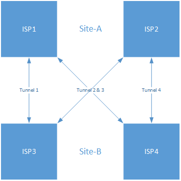
Here’s the configuration:
Site-A
set zone id 301 VPN-ISP1
set zone id 302 VPN-ISP2set zone “VPN-ISP1” vrouter “ISP1-vr”
set zone “VPN-ISP2” vrouter “ISP2-vr”set interface “tunnel.1” zone “VPN-ISP1”
set interface “tunnel.2” zone “VPN-ISP1”
set interface “tunnel.3” zone “VPN-ISP2”
set interface “tunnel.4” zone “VPN-ISP2”set interface tunnel.1 ip 192.168.1.1/24
set interface tunnel.2 ip 192.168.2.1/24
set interface tunnel.3 ip 192.168.3.1/24
set interface tunnel.4 ip 192.168.4.1/24set flow reverse-route clear-text prefer
set flow reverse-route tunnel alwaysset ike gateway “ISP1-to-SiteB-ISP3” address 2.2.1.2 Main outgoing-interface “ethernet0/0” preshare VPN_PSK sec-level standard
set ike gateway “ISP1-to-SiteB-ISP4” address 2.2.2.2 Main outgoing-interface “ethernet0/0” preshare VPN_PSK sec-level standard
set ike gateway “ISP2-to-SiteB-ISP3” address 2.2.1.2 Main outgoing-interface “ethernet0/1” preshare VPN_PSK sec-level standard
set ike gateway “ISP2-to-SiteB-ISP4” address 2.2.2.2 Main outgoing-interface “ethernet0/1” preshare VPN_PSK sec-level standardset vpn “ISP1-to-SiteB-ISP3” gateway “ISP1-to-SiteB-ISP3” no-replay tunnel idletime 0 sec-level standard
set vpn “ISP1-to-SiteB-ISP3” monitor rekey
set vpn “ISP1-to-SiteB-ISP3” bind interface tunnel.1set vpn “ISP1-to-SiteB-ISP4” gateway “ISP1-to-SiteB-ISP4” no-replay tunnel idletime 0 sec-level standard
set vpn “ISP1-to-SiteB-ISP4” monitor rekey
set vpn “ISP1-to-SiteB-ISP4” bind interface tunnel.2set vpn “ISP2-to-SiteB-ISP3” gateway “ISP2-to-SiteB-ISP3” no-replay tunnel idletime 0 sec-level standard
set vpn “ISP2-to-SiteB-ISP3” monitor rekey
set vpn “ISP2-to-SiteB-ISP3” bind interface tunnel.3set vpn “ISP2-to-SiteB-ISP4” gateway “ISP2-to-SiteB-ISP4” no-replay tunnel idletime 0 sec-level standard
set vpn “ISP2-to-SiteB-ISP4” monitor rekey
set vpn “ISP2-to-SiteB-ISP4” bind interface tunnel.4set policy id 1 from “Trust-ISP1” to “VPN-ISP1” “Any” “Any” “ANY” permit
set policy id 2 from “Trust-ISP2” to “VPN-ISP2” “Any” “Any” “ANY” permit
set policy id 3 from “VPN-ISP1” to “Trust-ISP1” “Any” “Any” “ANY” permit
set policy id 4 from “VPN-ISP2” to “Trust-ISP2” “Any” “Any” “ANY” permitSite-B
set zone id 301 VPN-ISP3
set zone id 302 VPN-ISP4set zone “VPN-ISP3” vrouter “ISP3-vr”
set zone “VPN-ISP4” vrouter “ISP4-vr”set interface “tunnel.1” zone “VPN-ISP3”
set interface “tunnel.2” zone “VPN-ISP3”
set interface “tunnel.3” zone “VPN-ISP4”
set interface “tunnel.4” zone “VPN-ISP4”set interface tunnel.1 ip 192.168.1.2/24
set interface tunnel.2 ip 192.168.2.2/24
set interface tunnel.3 ip 192.168.3.2/24
set interface tunnel.4 ip 192.168.4.2/24set flow reverse-route clear-text prefer
set flow reverse-route tunnel alwaysset ike gateway “ISP1-to-SiteA-ISP3” address 1.1.1.2 Main outgoing-interface “ethernet0/0” preshare VPN_PSK sec-level standard
set ike gateway “ISP1-to-SiteA-ISP4” address 1.1.2.2 Main outgoing-interface “ethernet0/0” preshare VPN_PSK sec-level standard
set ike gateway “ISP2-to-SiteA-ISP3” address 1.1.1.2 Main outgoing-interface “ethernet0/1” preshare VPN_PSK sec-level standard
set ike gateway “ISP2-to-SiteA-ISP4” address 1.1.2.2 Main outgoing-interface “ethernet0/1” preshare VPN_PSK sec-level standardset vpn “ISP1-to-SiteA-ISP3” gateway “ISP1-to-SiteA-ISP3” no-replay tunnel idletime 0 sec-level standard
set vpn “ISP1-to-SiteA-ISP3” monitor rekey
set vpn “ISP1-to-SiteA-ISP3” bind interface tunnel.1set vpn “ISP1-to-SiteA-ISP4” gateway “ISP1-to-SiteA-ISP4” no-replay tunnel idletime 0 sec-level standard
set vpn “ISP1-to-SiteA-ISP4” monitor rekey
set vpn “ISP1-to-SiteA-ISP4” bind interface tunnel.2set vpn “ISP2-to-SiteA-ISP3” gateway “ISP2-to-SiteA-ISP3” no-replay tunnel idletime 0 sec-level standard
set vpn “ISP2-to-SiteA-ISP3” monitor rekey
set vpn “ISP2-to-SiteA-ISP3” bind interface tunnel.3set vpn “ISP2-to-SiteA-ISP4” gateway “ISP2-to-SiteA-ISP4” no-replay tunnel idletime 0 sec-level standard
set vpn “ISP2-to-SiteA-ISP4” monitor rekey
set vpn “ISP2-to-SiteA-ISP4” bind interface tunnel.4set policy id 1 from “Trust-ISP3” to “VPN-ISP3” “Any” “Any” “ANY” permit
set policy id 2 from “Trust-ISP4” to “VPN-ISP4” “Any” “Any” “ANY” permit
set policy id 3 from “VPN-ISP3” to “Trust-ISP3” “Any” “Any” “ANY” permit
set policy id 4 from “VPN-ISP4” to “Trust-ISP4” “Any” “Any” “ANY” permit
There’s no difference between the configuration here of a normal numbered VPN tunnel, except the amount of tunnels needed. We now have 4 VPN tunnels up and running and you should be able to reach the IP addresses of the VPN tunnels between Site-A and Site-B.
Alright, so we now have ISP redundancy and load balancing on both sites and we’ve got 4 VPN tunnels up and running. All that remains is getting the client subnets routed over the VPN tunnels, so clients on both sites can communicate with each other. You could use static routes for this, but for scalability and ease of management, we’re going to use OSPF to exchange the routes.
Site-A & Site-B
set interface ethernet0/2 protocol ospf area 0.0.0.0
set interface ethernet0/2 protocol ospf enable
set interface ethernet0/3 protocol ospf area 0.0.0.0
set interface ethernet0/3 protocol ospf enableset interface tunnel.1 protocol ospf area 0.0.0.0
set interface tunnel.1 protocol ospf link-type p2mp
set interface tunnel.1 protocol ospf enable
set interface tunnel.1 protocol ospf cost 1
set interface tunnel.2 protocol ospf area 0.0.0.0
set interface tunnel.2 protocol ospf link-type p2mp
set interface tunnel.2 protocol ospf enable
set interface tunnel.2 protocol ospf cost 10set interface tunnel.3 protocol ospf area 0.0.0.0
set interface tunnel.3 protocol ospf link-type p2mp
set interface tunnel.3 protocol ospf enable
set interface tunnel.3 protocol ospf cost 10
set interface tunnel.4 protocol ospf area 0.0.0.0
set interface tunnel.4 protocol ospf link-type p2mp
set interface tunnel.4 protocol ospf enable
set interface tunnel.4 protocol ospf cost 1
This configuration enabled basic OSPF with 1 area and makes a primary bind of ISP1 to ISP3 and ISP2 to ISP4. If any of those fails, OSPF will recalculate the backup paths.
It may seem like a lot of configuration for simply adding a few routes, but it will pay off if you start using one of the sites as a hub and connect other branches to it. You can see I made some preparations for that by adding the ‘link-type p2mp’ (point to multi point). If you’re using this for 2 sites only and have no intention of connecting more sites, you could change the link-type to p2p for just a point to point connection.
And that’s it, you now have a double dual homed VPN setup on your Juniper SSG devices. Always test your configurations by performing proper fail overs. For instance, you can start by shutting down the WAN interfaces one by one and see how the routing of your internal subnets behaves within OSPF.
Good luck!
Leave a Reply