Cisco OTV (or Overlay Transport Virtualisation) is a technology inside Cisco Nexus switches (7K) for extending VLANs across a routed network. You can read all about OTV here and here. This post consists of an example configuration for a lab where you have a single Nexus 7K and you want to get OTV over multicast running between VDCs and comes from my CCIE study notes for when I was practicing with OTV. I’ve heard some people have issues with getting the multicast configuration working, so I figured I would share mine here.
First off, to create the illusion of a routed network, this will be an “OTV on a stick” type configuration and not a directly connected one (that would be too easy). Let’s take a look at the topology we want to create:
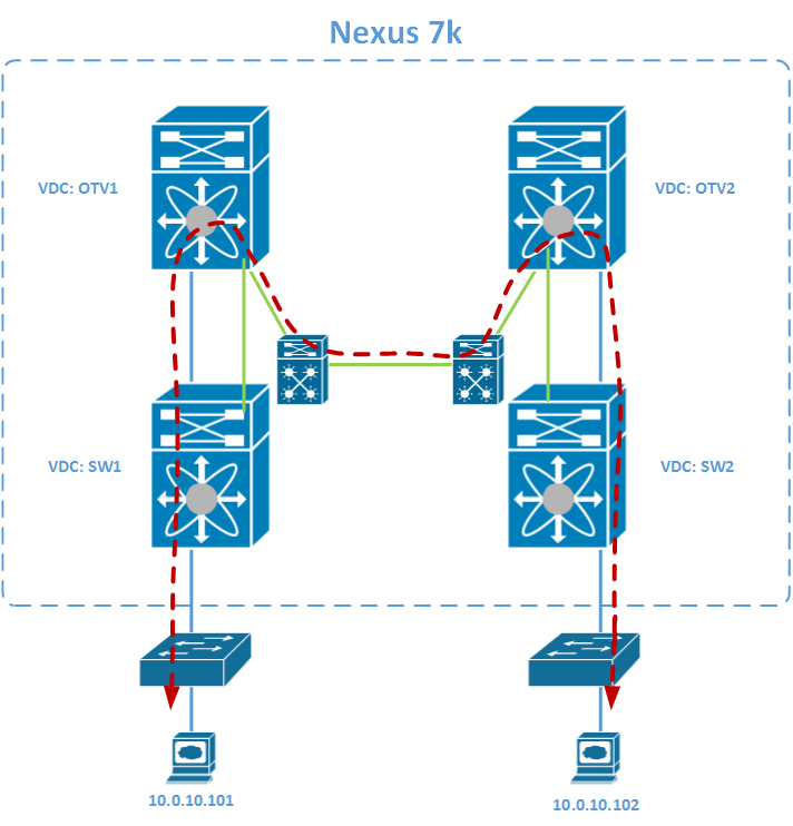
We want the two servers in 10.0.10.0/24 to reach each other through the routed fabric in between. The supervisor we’re using has a 4 VDC limit and in this example I will be using all 4. The smaller router icons are VRFs on the SW1 and SW2 VDCs which you will see return in the configuration.
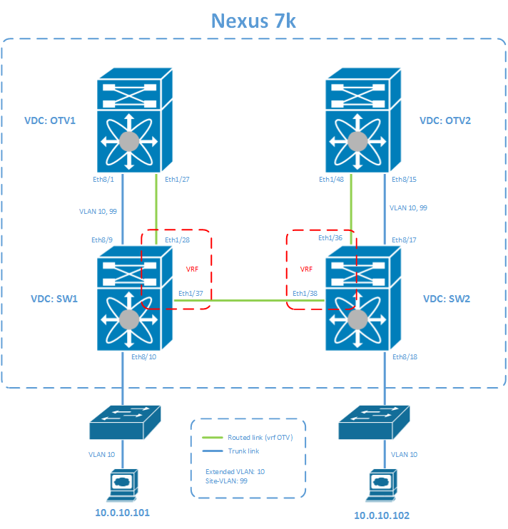
I’m going to assume you have a working knowledge of basic NX-OS, OSPF and OTV knowledge and have the VDCs set up, have the proper licenses, made the proper interface allocations (mind your M and F linecards and make sure absolutely no other connections are active and trunking, you’ll have a field day looking for why it doesn’t work otherwise) and can start from there. First, some basic information:
OTV Extended VLAN: 10
OTV Site-VLAN: 99
OTV Site-IDs: 0x1 & 0x2
OTV Control: 239.1.1.1
OTV Data Range: 232.1.1.0/24
Let’s begin with numbering all the interfaces and creating the OSPF network:
OTV1
feature ospf

! Define VLANs
vlan 10
  name SERVERS
vlan 99
  name OTV-SITE

! Enable OSPF
router ospf 1
  log-adjacency-changes

! Join interface
interface Ethernet1/27
  ip address 172.16.0.2/30
  ip ospf network point-to-point
  ip router ospf 1 area 0.0.0.0
  no shutdown

! Internal interface
interface Ethernet8/1
  switchport mode trunk
  switchport trunk allowed vlan 10,99
  no shutdown
SW1
feature ospf

! Define VLANs
vlan 10
  name SERVERS
vlan 99
  name OTV-SITE

! Define vrf context for separating 'intra-dc' traffic from local traffic
vrf context OTV

! Used for OSPF router-id
interface loopback0
  vrf member OTV
  ip address 1.1.1.1/32

! OSPF redistribution for following ranges
ip prefix-list OSPF-REDIST permit 172.16.0.0/30
ip prefix-list OSPF-REDIST permit 1.1.1.1/32

route-map OSPF_REDIST permit 10
  match ip address prefix-list OSPF_REDIST

! Have OSPF send default gateway to following peers:
ip prefix-list OSPF_DEF_ROUTE permit 172.16.0.0/30
route-map OSPF_DEF_ROUTE permit 10
  match ip address prefix-list OSPF_DEF_ROUTE

! Enable OSPF and redistribute proper prefixes and default gateway to OTV VDC
router ospf 1
  default-information originate always route-map OSPF_DEF_ROUTE
  redistribute direct route-map OSPF_REDIST
  log-adjacency-changes
  vrf OTV

! Link to OTV1 (Join interface)
interface Ethernet1/28
  vrf member OTV
  ip address 172.16.0.1/30
  ip ospf network point-to-point
  ip router ospf 1 area 0.0.0.0
  no shutdown

! Link to SW2
interface Ethernet1/37
  vrf member OTV
  ip address 192.168.0.1/30
  ip ospf network point-to-point
  ip router ospf 1 area 0.0.0.0
  no shutdown

! Link to OTV1 (Internal interface)
interface Ethernet8/9
  switchport mode trunk
  switchport trunk allowed vlan 10,99
  no shutdown

! Link to access switch
interface Ethernet8/10
  switchport mode trunk
  switchport trunk allowed vlan 10
  no shutdown
SW1
feature ospf

! Define VLANs
vlan 10
  name SERVERS
vlan 99
  name OTV-SITE

! Define vrf context for separating 'intra-dc' traffic from local traffic
vrf context OTV

! Used for OSPF router-id
interface loopback0
  vrf member OTV
  ip address 2.2.2.2/32

! OSPF redistribution for following ranges
ip prefix-list OSPF-REDIST permit 172.16.1.0/30
ip prefix-list OSPF-REDIST permit 2.2.2.2/32

route-map OSPF_REDIST permit 10
  match ip address prefix-list OSPF_REDIST

! Have OSPF send default gateway to following peers:
ip prefix-list OSPF_DEF_ROUTE permit 172.16.1.0/30
route-map OSPF_DEF_ROUTE permit 10
  match ip address prefix-list OSPF_DEF_ROUTE

! Enable OSPF and redistribute proper prefixes and default gateway to OTV VDC
router ospf 1
  router-id 2.2.2.2
  default-information originate always route-map OSPF_DEF_ROUTE
  redistribute direct route-map OSPF_REDIST
  log-adjacency-changes
  vrf OTV

! Link to OTV2 (Join interface)
interface Ethernet1/36
  vrf member OTV
  ip address 172.16.1.1/30
  ip ospf network point-to-point
  ip router ospf 1 area 0.0.0.0
  no shutdown

! Link to SW1
interface Ethernet1/38
  vrf member OTV
  ip address 192.168.0.2/30
  ip ospf network point-to-point
  ip router ospf 1 area 0.0.0.0
  no shutdown

! Link to OTV2 (Internal interface)
interface Ethernet8/17
  switchport mode trunk
  switchport trunk allowed vlan 10,99
  no shutdown

! Link to access switch
interface Ethernet8/18
  switchport mode trunk
  switchport trunk allowed vlan 10
  no shutdown
OTV2
feature ospf

! Define VLANs
vlan 10
  name SERVERS
vlan 99
  name OTV-SITE

! Enable OSPF
router ospf 1
  log-adjacency-changes

! Join interface
interface Ethernet1/48
  ip address 172.16.1.2/30
  ip ospf network point-to-point
  ip router ospf 1 area 0.0.0.0
  no shutdown

! Internal interface
interface Ethernet8/15
  switchport mode trunk
  switchport trunk allowed vlan 10,99
  no shutdown
With that out of the way you should have a routed network and OTV1 should be able to reach OTV2:
OTV1# ping 172.16.1.2
PING 172.16.1.2 (172.16.1.2): 56 data bytes
64 bytes from 172.16.1.2: icmp_seq=0 ttl=254 time=48.052 ms
64 bytes from 172.16.1.2: icmp_seq=1 ttl=254 time=4.923 ms
64 bytes from 172.16.1.2: icmp_seq=2 ttl=254 time=20.752 ms
64 bytes from 172.16.1.2: icmp_seq=3 ttl=254 time=2.935 ms
64 bytes from 172.16.1.2: icmp_seq=4 ttl=254 time=4.965 ms

--- 172.16.1.2 ping statistics ---
5 packets transmitted, 5 packets received, 0.00% packet loss
round-trip min/avg/max = 2.935/16.325/48.052 ms
Now it’s time for the multicast and OTV configuration. Disclaimer: I am not a multicast expert, but I know enough to get it to work. It might be very well that there is a more efficient way of setting this up, this is just what I did to get it working.
OTV1
feature otv

! Define local OTV identifiers
otv site-vlan 99
otv site-identifier 0x1

! Join interface
interface Ethernet1/27
  ip igmp version 3

! Define OTV overlay with join interface, the extended VLAN and multicast addresses
interface Overlay0
  otv join-interface Ethernet1/27
  otv control-group 239.1.1.1
  otv data-group 232.1.1.0/24
  otv extend-vlan 10
  no shutdown
SW1
! Enable multicast routing between SW1 and SW2
feature pim

ip pim send-rp-announce loopback0 group-list 224.0.0.0/4
ip pim auto-rp mapping-agent loopback0
ip pim ssm range 232.0.0.0/8
ip pim auto-rp forward listen

! Link to OTV1 (Join interface)
interface Ethernet1/28
  ip pim sparse-mode
  ip igmp version 3

! Link to SW2
interface Ethernet1/37
  ip pim sparse-mode
  ip igmp version 3

interface loopback0
  ip pim sparse-mode
SW2
! Enable multicast routing between SW1 and SW2
feature pim

ip pim send-rp-announce loopback0 group-list 224.0.0.0/4
ip pim auto-rp mapping-agent loopback0
ip pim ssm range 232.0.0.0/8
ip pim auto-rp forward listen

! Link to OTV2 (Join interface)
interface Ethernet1/36
  ip pim sparse-mode
  ip igmp version 3

! Link to SW1
interface Ethernet1/38
  ip pim sparse-mode
  ip igmp version 3

interface loopback0
  ip pim sparse-mode
OTV2
feature otv

! Define local OTV identifiers
otv site-vlan 99
otv site-identifier 0x2

! Join interface
interface Ethernet1/48
  ip igmp version 3

! Define OTV overlay with join interface, the extended VLAN and multicast addresses
interface Overlay0
  otv join-interface Ethernet1/48
  otv control-group 239.1.1.1
  otv data-group 232.1.1.0/24
  otv extend-vlan 10
  no shutdown
If you’ve come this far, you’ve got the following topology:
At this time, you should have a working OTV adjacency between OTV1 and OTV2. Don’t freak out when there’s no connectivity at first, as OTV adjacencies could take a while before they are actually forwarding. If there’s no connectivity, check the output of this command:
OTV1# sh otv vlan
OTV Extended VLANs and Edge Device State Information (* - AED)
Legend:
(NA) - Non AED, (VD) - Vlan Disabled, (OD) - Overlay Down
(DH) - Delete Holddown, (HW) - HW: State Down
(NFC) - Not Forward Capable
VLAN Auth. Edge Device                   Vlan State             Overlay
---- ----------------------------------- ---------------------- -------
10   OTV1                                inactive(33 s left)    Overlay0
If your output is similar to the above output, wait patiently for the countdown to finish. After that grace period the VLAN status should switch to active.
If everything is working correctly, you should have these types of output:
OTV1# sh otv adjacency
Overlay Adjacency database

Overlay-Interface Overlay0 :
Hostname  System-ID        Dest Addr    Up Time    State
OTV2      001e.bd27.c000   172.16.1.2   00:11:21   UP

OTV1# sh otv vlan
OTV Extended VLANs and Edge Device State Information (* - AED)
Legend:
(NA) - Non AED, (VD) - Vlan Disabled, (OD) - Overlay Down
(DH) - Delete Holddown, (HW) - HW: State Down
(NFC) - Not Forward Capable
VLAN Auth. Edge Device                   Vlan State             Overlay
---- ----------------------------------- ---------------------- -------
10   OTV1                                active                 Overlay0
If your adjacency is not online, you have some troubleshooting to do. Here’s a few links that could help you in that case:
- Cisco Live on Advanced OTV (there’s a troubleshooting section)
- Troubleshooting OTV Adjacency
- Troubleshooting ARP issues across OTV
- OTV Silent Host Connectivity Problem
October 13, 2015 at 17:40
Hello there…
Im also looking to setting up otv in a lab…but luckily, i have two separate 77ks to mess with…my question is, what is the reason for connecting sw1 and sw2?…also, is the multicast routing b/w sw1 and sw2 needed since that is done at the aed vdc?
thanks in advance
October 18, 2015 at 16:39
Hi Sam,
Thanks for your message. As for your questions, I’ll try to answer here. The reason for connecting sw1 and sw2 is to form essentially what is your dark fiber running between locations. This is where your traffic goes from location 1 to location 2. There is no way to create a ‘virtual wire’ between sw1 and sw2 internally, so you have to use a physical cable.
Multicast is definitely also necessary on the sw1 and sw2 as that is the backbone of OTV. You’re right that multicast is used in the OTV VDCs, but it uses it to reach the other OTV instance on the other location. If your transport devices (sw1 and sw2) do not route multicast, the OTV instances won’t be able to talk to each other and form the OTV adjacency.
Hope that helps.