With the release of vRealize Network Insight 3.6, the flow analyser inside vRNI now supports external sources for NetFlow. This means you can perform micro segmentation planning on physical servers (before you migrate them to virtual) and create deep insight into what network traffic is going through your entire network (and not just limited to what’s happening in your virtual network).
Currently, NetFlow versions 5, 7, 9 and IPFIX are supported. Getting started with NetFlow in vRNI is pretty easy, but it is slightly more complicated than regular data sources.
Getting Started
I say it’s slightly more complicated, because you have to have a dedicated Collector VM (previously known as Proxy VM) for NetFlow only. The deployment process of this Collector is a bit different, I’ll guide you through the steps below.
First, get the regular Collector VM OVA file, the same one you used to deploy the Collector that collects data from your vCenter, NSX, etc. Get ready to deploy it via vCenter, but first follow these steps to get a shared secret:
- Login to vRNI
- Go to the settings (either type “settings” in the search bar or use the menu on the top right)
- Select Accounts and Data Sources
- Click the Add Source button
- Choose Netflow Collector as the data source type (on the bottom)
- Click the Add Collector VM button. This will display the following popup:
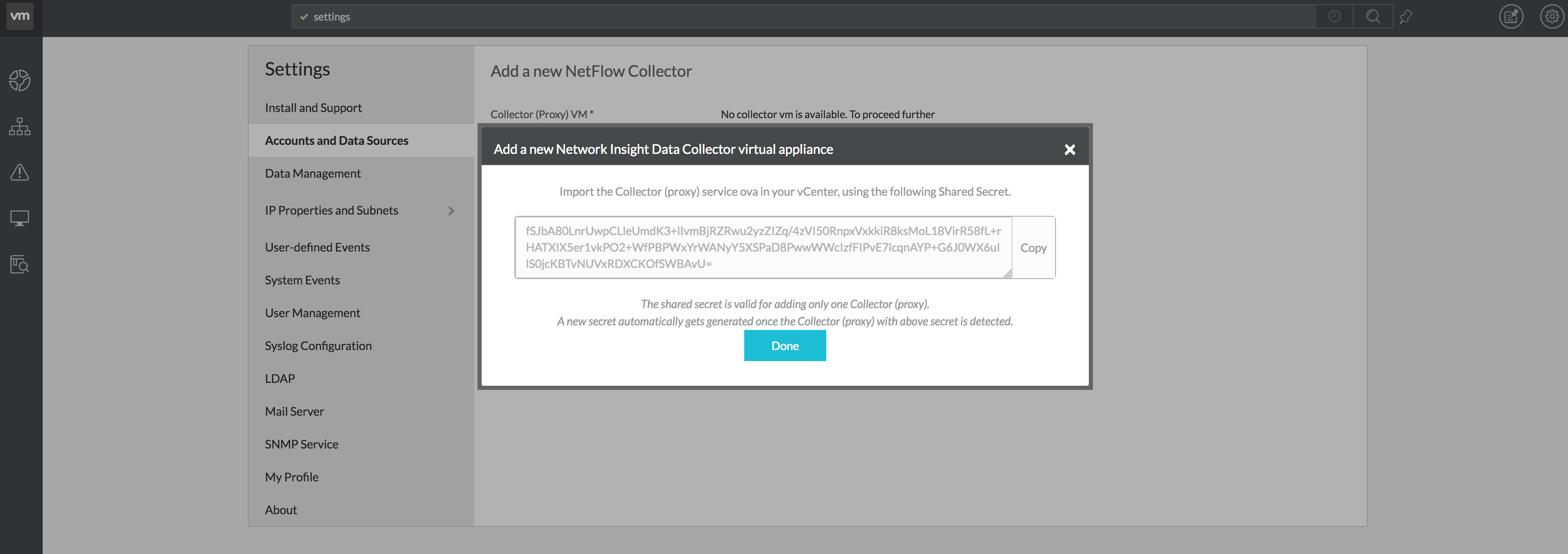
Deploying the Collector VM
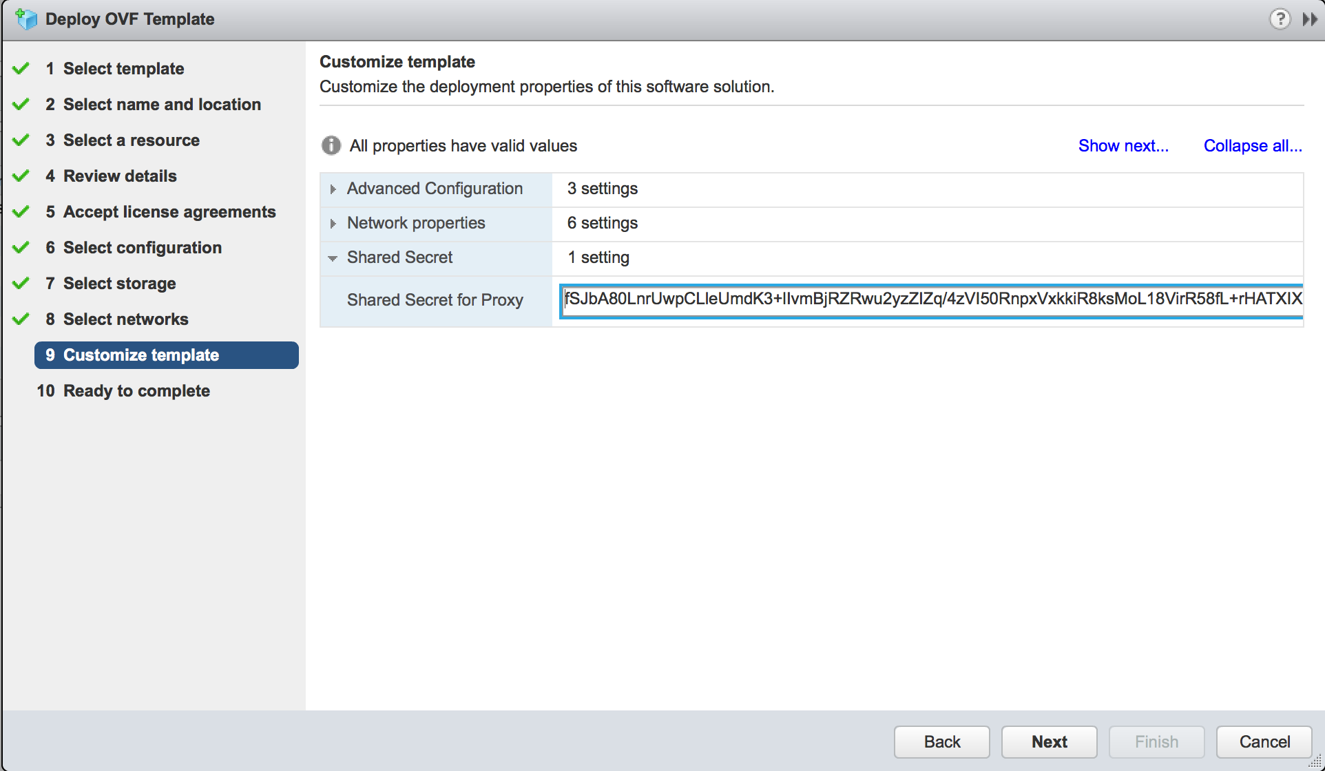
After you’ve generated the shared secret for the Collector VM, you can go ahead and deploy that OVA via vCenter. I’m not going to go through all steps, assuming you know how to deploy an OVA. Remember to select Thin Provisioning. You will get a couple of template customisation options, mostly around network settings, but the last option is the most important one; the shared secret. Here you want to input the shared secret you just generated in the vRNI UI.
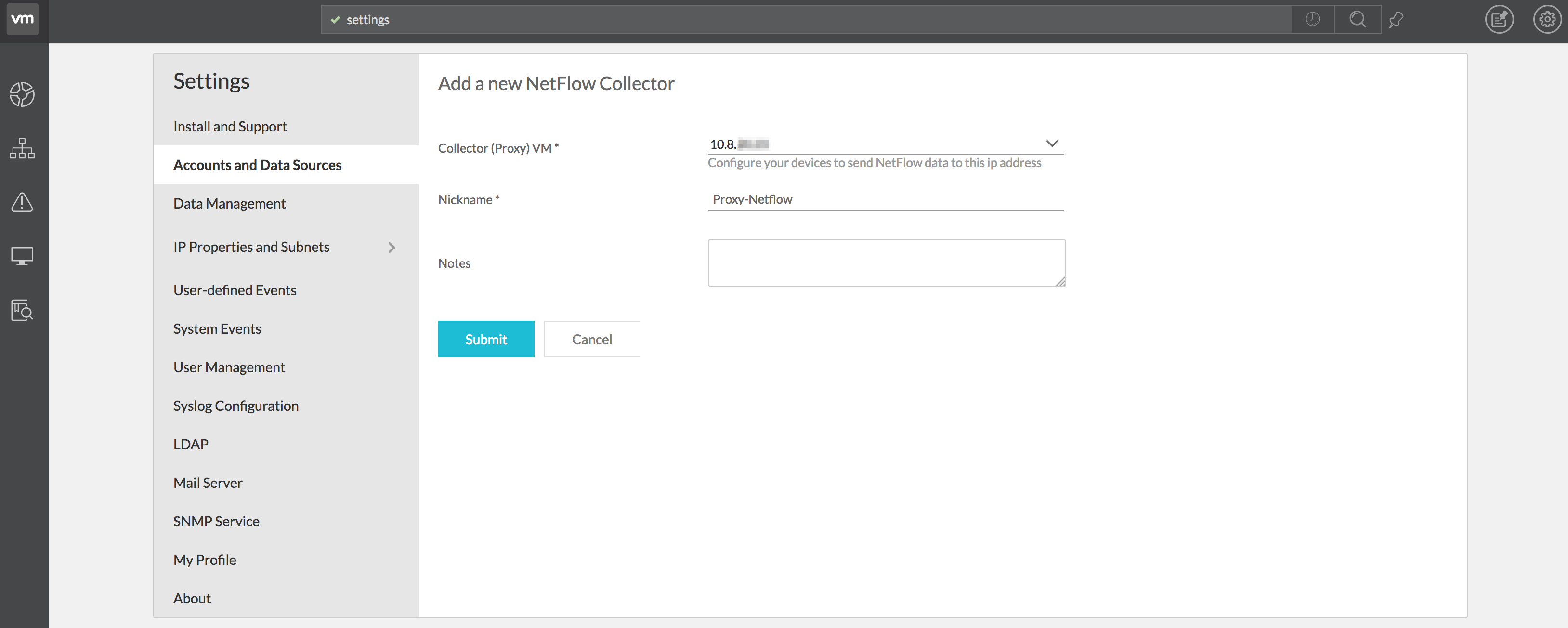
If everything looks good, deploy the Collector and go get some coffee. It takes a couple of minutes to deploy the OVA and the boot sequence needs to be completed before you can continue. It takes 10 to 15 minutes total. Don’t be like Fred, don’t stare at the progress bars. Anyway, when it’s done with all that it needs to do, it will show up in the vRNI UI automagically. When it does, give it a nickname and optionally some notes about the Collector. Click the Submit button when you’re done.
You can check if you’re successful by looking at your data source overview and the NetFlow data source turns up and there’s a timestamp on the Last Collection value.
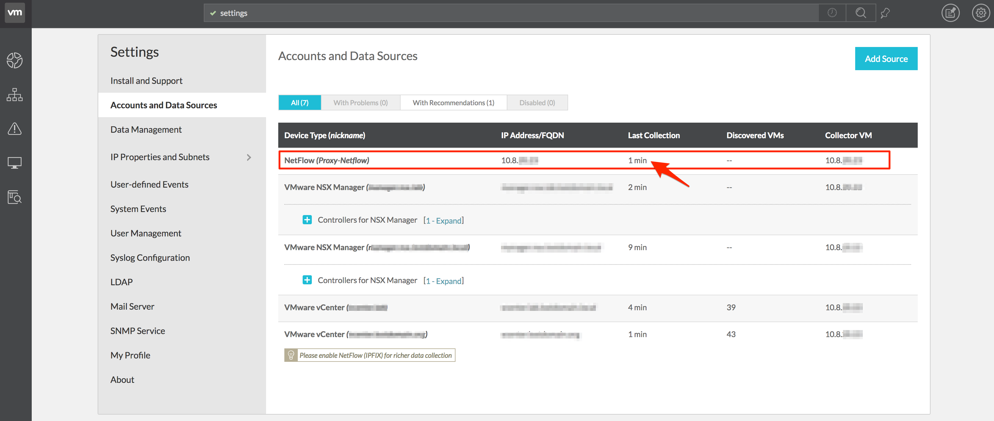
And that’s it, vRealize Network Insight is ready for NetFlow ingestion. Point your NetFlow streams to the IP address of the newly created Collector VM.
Verification
Alright, so now you have the NetFlow Collector running and it’s supposed to gather flow data to present back to you. If you’ve already configured your switch to send NetFlow to your NetFlow Collector VM though. If you haven’t, there are a couple examples at the bottom here.
There’s a search query to test if your vRNI is actually collecting physical NetFlow:
flow where Flow Type = 'Source is Physical' and Flow Type = 'Destination is Internet'
I don’t think I have to explain what you’re looking at. ?
Creating More Context
Currently, vRNI does not resolve physical IP addresses to names (Also, who has their complete network correctly configured for forward DNS, let alone reverse DNS?). The functionality will be more automated in the future (like reading from a CMDB & IPAM, is my best hope/guess), but for now you can manually create more context for the physical flows you’ll be seeing in the UI.
There are two options to do this in the Settings page, under IP Properties and Subnets.
Physical IP and DNS Mappings
You can upload your Bind zones to vRNI so that it can use DNS names instead of IP addresses. If you don’t have Bind as your DNS server (have to admit, it’s pretty old), you can also upload a simple CSV file with your DNS records in it. Examples of this CSV file and the Bind zones can be found in a downloadable zip file.
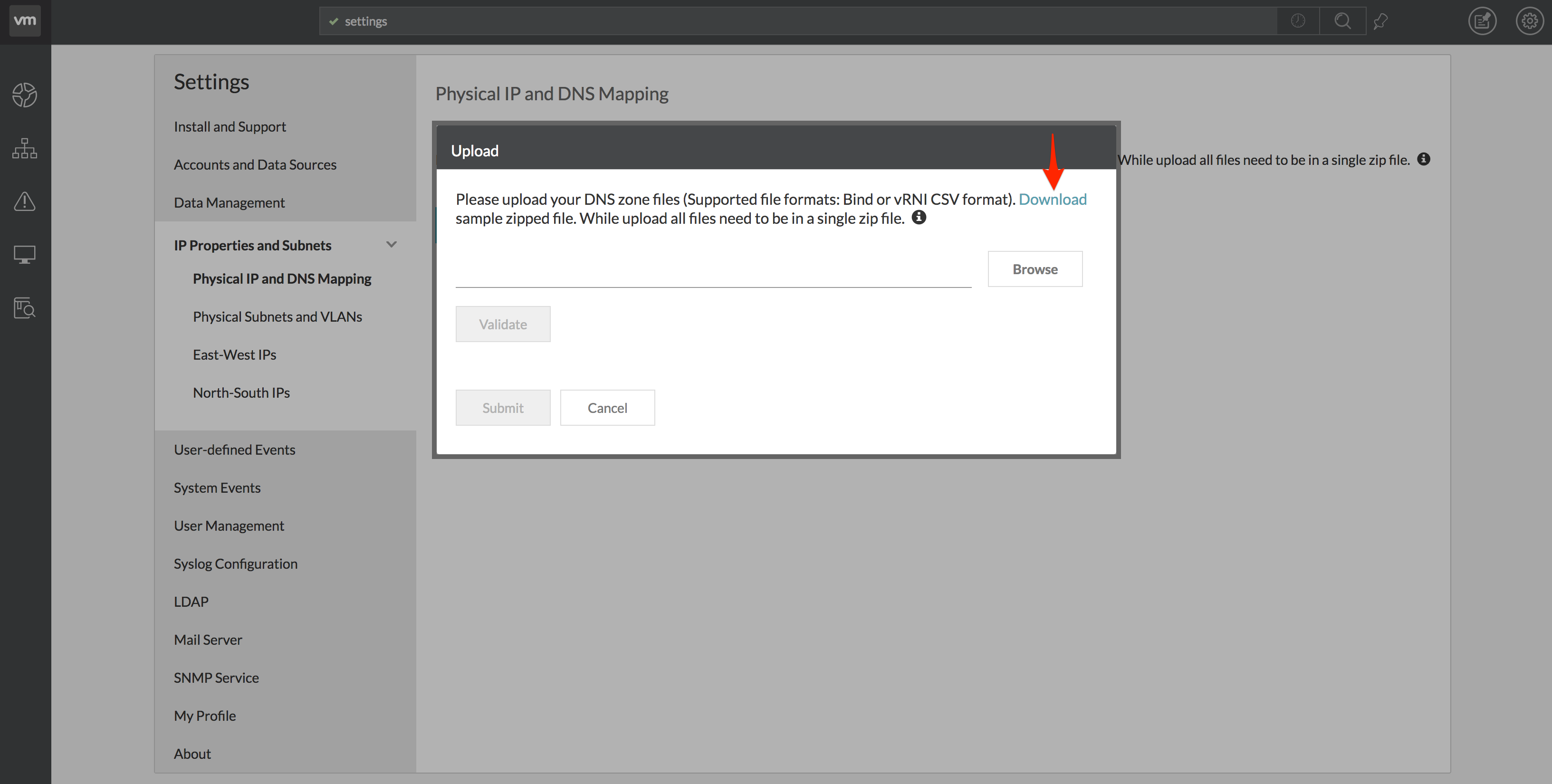
Remember to zip up whichever format you use, even if it’s just 1 file.
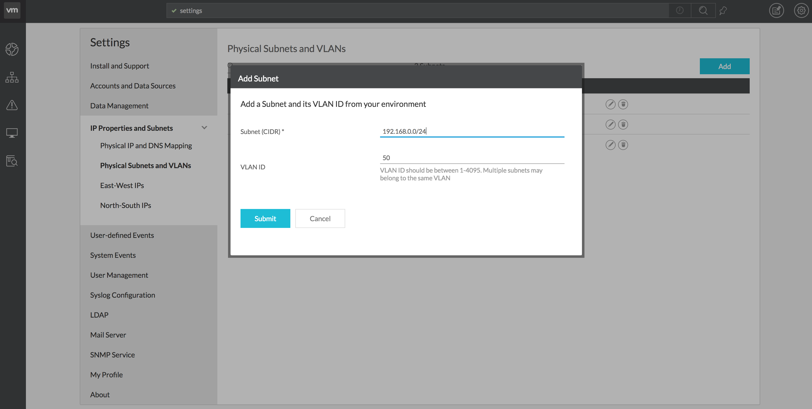
Physical Subnets and VLANs
The other option to provide more feedback can be a bit more confusing. You can also manually map subnets to IP Subnets. I can hear what you’re thinking: “Isn’t vRNI supposed to do this automatically via its data sources?!?!?” – well, yes. If the NetFlow is coming from a supported data source, it will indeed automatically translate the IP Subnets to a VLAN. But here’s the thing; NetFlow is pretty universal and there’s a somewhat limited (although pretty large) list of supported switches and routers as a data source within vRNI. If you decide to send NetFlow from a switch or router that is not on the supported data source list, vRNI doesn’t know what IP Subnet belongs to what VLAN. That’s why you can configure them manually.
The process is pretty simply; on the Physical Subnets and VLANs settings page, click the Add button. Then enter a Subnet and VLAN ID and press Submit.
NetFlow Configuration
Here are a couple of examples on what configuration is needed on certain switch types. Replace $Collector_VM_IP with the IP address of your vRNI NetFlow Collector.
Disclaimer: Verify commands before you enter them into your equipment. I haven’t been able to test all of these, some are from documentation and theoretical.
ASA Firewall, Cisco
flow-export destination inside $Collector_VM_IP 2055
flow-export template timeout-rate 1
flow-export delay flow-create 60
access-list netflow-export extended permit ip any any
class-map netflow-export-class
match access-list netflow-export
policy-map global_policy
class netflow-export-class
flow-export event-type all destination $Collector_VM_IP
service-policy global_policy global
Cisco Catalyst
flow record NetFlow-input
    description IPv4 NetFlow
    match ipv4 source address
    match ipv4 destination address
    match transport source-port
    match transport destination-port
    match ipv4 protocol
    match interface input
    match ipv4 tos
    match datalink mac output
    match flow direction
    collect interface output
    collect counter bytes long
    collect counter packets long
    collect transport tcp flags
    collect timestamp absolute first
    collect timestamp absolute last

flow record NetFlow-output
    description IPv4 NetFlow
    match ipv4 source address
    match ipv4 destination address
    match transport source-port
    match transport destination-port
    match ipv4 protocol
    match interface output
    match ipv4 tos
    match datalink mac output
    match flow direction
    collect interface input
    collect counter bytes long
    collect counter packets long
    collect transport tcp flags
    collect timestamp absolute first
    collect timestamp absolute last

flow exporter vRNI_Collector_VM
    description Export to vRNI
    destination $Collector_VM_IP
    source $Source_Interface
    transport udp 2055

flow monitor vRNI_Monitor_Input
    description vRNI Ingress Monitor
    exporter vRNI_Collector_VM
    record NetFlow-input
    cache timeout active 60

flow monitor vRNI_Monitor_Output
    description vRNI Egress Monitor
    exporter vRNI_Collector_VM
    record NetFlow-output
    cache timeout active 60

! Repeat this for any interface you want to capture
interface GigabitEthernet1/0/1
    ip flow monitor vRNI_Monitor_Input input
    ip flow monitor vRNI_Monitor_Output output
Cisco Nexus
switch(config)# feature netflow
switch(config)# flow timeout active 60
switch(config)# flow timeout inactive 15

switch(config)# flow exporter netflow_to_vRNI
switch(config-flow-exporter)# description Export NetFlow to vRealize Network Insight
switch(config-flow-exporter)# destination $Collector_VM_IP
switch(config-flow-exporter)# source $Source_Interface
switch(config-flow-exporter)# transport udp 2055
switch(config-flow-exporter)# version 9

switch(config)# flow monitor netflow_vRNI_v9
switch(config-flow-monitor)# record netflow-original
switch(config-flow-monitor)# exporter netflow_to_vRNI

! Repeat this for any interface you want to capture
switch(config)# interface
switch(config-if)# ip flow monitor netflow_vRNI_v9 input
Extreme
configure ip-fix ip-address $Collector_VM_IP protocol udp L4-port 2055 vr "VR-Default"
configure ip-fix source ip-address $Source_IP vr "VR-Default"

! Configure port 47 and 48 for IPFIX
configure ip-fix ports 47 ingress-and-egress
enable ip-fix ports 47 ipv4
configure ip-fix ports 48 ingress-and-egress
enable ip-fix ports 48 ipv4
FortiGate
config system netflow
    set collector-ip $Collector_VM_IP
    set collector-port 2055
    set source-ip $Source_IP
    set active-flow-timeout 1
    set inactive-flow-timeout 15

! Repeat this for any interface you want to capture
config system interface
    edit
        set netflow-sampler both
    end
end
MikroTik
/ip traffic-flow
ip traffic-flow> set enabled=yes
ip traffic-flow> /target
ip traffic-flow target> add dst-address=$Collector_VM_IP port=2055 version=9
Palo Alto
This is policy based via de UI, here’s a link to their manual.
Ubiquiti EdgeMax (EdgeRouter Lite)
set system flow-accounting netflow server $Collector_VM_IP
set system flow-accounting netflow version 9
! Repeat this for any interface you want to capture
set system flow-accounting interface eth0

commit
save
Any additions or corrections are appreciated!
Leave a Reply