VCIX-NV Objective 2.1 – Create and Administer Logical Switches
This post is part of my VMware VCIX-NV Study Guide and covers the Logical Switches in NSX.
Documentation
Index
- Create/Delete Logical Switches
- Assign and configure IP addresses
- Connect a Logical Switch to an NSX Edge
- Deploy services on a Logical Switch
- Connect/Disconnect virtual machines to/from a Logical Switch
- Test Logical Switch connectivity
What is a Logical Switch? In previous versions of vSphere, you had two networking options for virtual machines, which were a portgroup on a standard vSwitch or a portgroup on a Distributed vSwitch. These usually consisted of a logical wire mapped to a specific VLAN on the physical network. This way, you can isolate virtual machines or multiple tenant from each other. The NSX Logical Switch also creates a logical separation between different logical switches, but uses the VXLAN technology to realise this.
This means the underlay network merely consists of 1 VLAN for the data transport (or even routed subnets), where VXLAN facilitates the network isolation between different logical switches. This allows the administrators to create separated networks for virtual machines on the fly.
The logical switches are created inside Transport Zones, which in turn spans the logical switches across all clusters that a transport zone contains. A logical switch gets a dedicated VXLAN number for traffic identification. This number comes from the Segment ID pool which you need to configure before creating any logical switches.
Create/Delete Logical Switches
Requirements:
- NSX Base components installed and configured.
- Prepared clusters and ESXi nodes.
VMware Documentation: Add a Logical Switch
Add a Logical Switch
- Login to your vSphere Web Client.
- Navigate to “Networking & Security” and select the “Logical Switches” menu.
- Click the ”+” icon to start adding a logical switch.
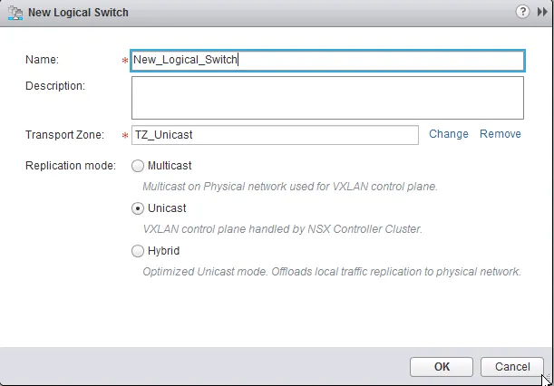
- Give the new logical switch a name and an optional description, select the transport zone you want to create this logical switch in.
- Usually you should leave the replication mode as the default of the transport zone, but you have an option to create an exception per logical switch.
- Click “OK”.
Remove a Logical Switch Before removing a logical switch, make sure there are no virtual machines attached to the switch.
- Login to your vSphere Web Client.
- Navigate to “Networking & Security” and select the “Logical Switches” menu.
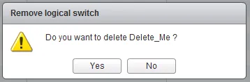
- Right click the logical switch you want to remove and select “Remove”. Confirm deletion.
Assign and configure IP addresses
It’s not real clear to me what VMware means with this requirement, as nothing is defined in the NSX documentation, any design guides or community discussion. You can’t assign an IP address to a logical switch, as it’s simply a layer-2-like boundary for virtual machines. Each virtual machine should have an IP address (IPv4 or IPV6) and there should be some type of gateway attached to the logical switch as well. The gateway can be a Logical Distributed Router or an Edge Services gateway, which will have an IP address as well.
I’m guessing that if you can assign IP addresses to virtual machines (method depends on the operation system) and know how to deploy NSX Edges and assign IP addresses there, you have met this requirement.
Connect a Logical Switch to an NSX Edge
Requirements:
- Existing NSX Logical Switch.
- Existing NSX Edge gateway.
VMware Documentation: Connect a Logical Switch to an NSX Edge
To enable network connectivity (routing) inside your NSX network, you need NSX Edge gateways to build a bridge between logical switches. You can attach either type of NSX Edge (Logical Distributed Router or Edge Services Gateway) to a logical switch, the procedure is the same.
Add a NSX Edge to a Logical Switch
- Login to your vSphere Web Client.
- Navigate to “Networking & Security” and select the “Logical Switches” menu.
- Select the Logical Switch to which you want to add the NSX Edge and click the Edge icon:

- Select the NSX Edge you want to add and click “Next”.
- Select the interface of the NSX Edge that will be attached to the logical switch and click “Next”.
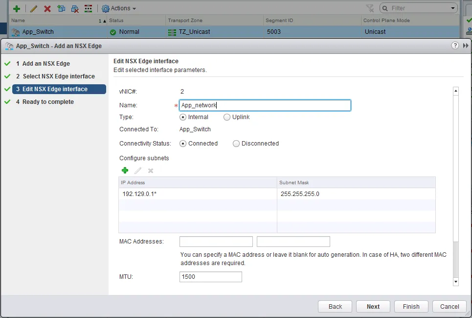
- Edit the details of the NSX Edge interface; give it a name, indicate whether this will be an internal or an uplink port, set the default connectivity status and optionally change the MTU size if needed.
- Add IP addresses by click the ”+” icon in the “Configure subnets” view.
- Click the ”+” icon again in the popup window to add the IP address, select which IP address is the primary interface IP address and fill out the prefix length of the subnet. Click “OK” when done.
- Click “Next” when you’re finished with the NSX Edge interface configuration.
- Review your configuration and click “Finish” to add the NSX Edge to your logical switch.
Deploy services on a Logical Switch
Requirements:
- Existing NSX Logical Switch.
- Existing Service Profile.
VMware Documentation: Deploy Services on a Logical Switch
Service profiles contain third party features that can be attached to a logical switch, the same as an Edge Services Gateway can be attached to a logical switch. Before you can attach a service profile, you have to create it first. Creating a service profile is out of scope for this procedure, the following only describes the attaching of a service profile to a logical switch.
Add Services to a Logical Switch
- Login to your vSphere Web Client.
- Navigate to “Networking & Security” and select the “Logical Switches” menu.
- Select the Logical Switch to which you want to add the Service and click the Service icon:

- Select Service from the dropdown menu in the popup window, attach any filters if required and click “OK”.
Connect/Disconnect virtual machines to/from a Logical Switch
Requirements:
- Existing NSX Logical Switch and a few virtual machines.
VMware Documentation: Connect Virtual Machines to a Logical Switch
Now to the good part, adding virtual machines to a logical switch. This is what it is all about, adding virtual machines to the logical switch so they are able to use the shiny new and advanced features of the NSX Edge Services Gateway or Logical Distributed Router, or just separating their internal network traffic.
You are going to have to think a little bit different then regular portgroup management on a VM though, as you need to do this from the logical switch, not from the VM perspective. Usually you edit the VM, go to the network interface and select the portgroup you want to place the VM in there. With NSX, you do it from the Logical Switch management pane, select a logical switch and add VMs to it.
Adding VMs to a Logical Switch
- Login to your vSphere Web Client.
- Navigate to “Networking & Security” and select the “Logical Switches” menu.
- Select the Logical Switch to which you want to add VMs and click the “Add Virtual Machine” icon:

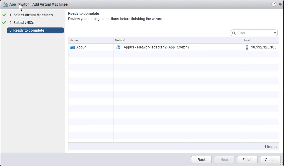
- Select the VMs you want to connect. Search for specific VMs by using the ‘Filter’ box. Click “Next” when done.
- Select the vNICs per VM which you want to connect and click “Next”.
- Review the changes you are making and click “Finish”.
Removing VMs from a Logical Switch Removing VMs from a logical switch is pretty much the same as adding them to a logical switch.
- Login to your vSphere Web Client.
- Navigate to “Networking & Security” and select the “Logical Switches” menu.
- Select the Logical Switch to which you want to remove VMs from and click the “Remove Virtual Machine” icon:

- Select the VMs you want to disconnect. Search for specific VMs by using the ‘Filter’ box. Click “OK” when done.

Test Logical Switch connectivity
Requirements:
- Existing NSX Logical Switch.
VMware Documentation: Test Logical Switch Connectivity
There are certain network requirements that a VXLAN transport network needs to fulfil before a transport zone and the logical switches inside will actually work. NSX provides troubleshooting tools to detect whether these requirements have been met, or if there’s an issue somewhere. Testing the logical switch connectivity between ESXi nodes should be a standard for adding new logical switches.
Testing Logical Switch connectivity
- Login to your vSphere Web Client.
- Navigate to “Networking & Security” and select the “Logical Switches” menu.
- Click the logical switch you want to test and select the “Hosts” tab after that.
- Select a host and click “Test Connectivity” in the “More Actions” menu.
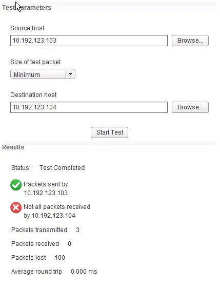
- The popup window allows you to test the connectivity. The earlier selected host will appear as Source Host and you need to select a Destination Host.
- Select the size of the test packets; the “VXLAN standard” packet is 1550 bytes.
- Click “Start Test” to start testing.
- After sending the test packets the result will appear below. Here is an example of a failed test: